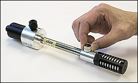
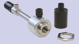
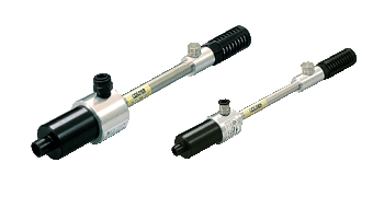
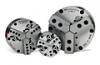
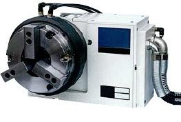
POWER-CHECK ý§√◊ËÕß¡◊Õ«—¥·√ߥ÷ߢÕßý§√◊ËÕß®—°√ CNC Machining Center
µ—«·∑π®”ÀπË“¬ ‘π§È“ OTT-JAKOB Power-Check 2 OTT-JAKOB POWER-CHECK ý§√◊ËÕß¡◊Õ«—¥·√ߥ÷ߢÕßý§√◊ËÕß®—°√ CNC Machining Center µ—«·∑π®”ÀπË“¬ ‘π§È“ OTT-JAKOB Power-Check 2 OTT-JAKOB POWER-CHECK ý§√◊ËÕß¡◊Õ«—¥·√ߥ÷ߢÕßý§√◊ËÕß®—°√ CNC Machining Center µ—«·∑π®”ÀπË“¬ ‘π§È“ OTT-JAKOB Power-Check 2 OTT-JAKOB POWER-CHECK ý§√◊ËÕß¡◊Õ«—¥·√ߥ÷ߢÕßý§√◊ËÕß®—°√ CNC Machining Center
µ—«·∑π®”ÀπË“¬ ‘π§È“ OTT-JAKOB Power-Check 2 OTT-JAKOB POWER-CHECK ý§√◊ËÕß¡◊Õ«—¥·√ߥ÷ߢÕßý§√◊ËÕß®—°√ CNC Machining Center µ—«·∑π®”ÀπË“¬ ‘π§È“ OTT-JAKOB Power-Check 2 OTT-JAKOB POWER-CHECK ý§√◊ËÕß¡◊Õ«—¥·√ߥ÷ߢÕßý§√◊ËÕß®—°√ CNC Machining Center µ—«·∑π®”ÀπË“¬ ‘π§È“ OTT-JAKOB Power-Check 2 OTT-JAKOB POWER-CHECK ý§√◊ËÕß¡◊Õ«—¥·√ߥ÷ߢÕßý§√◊ËÕß®—°√ CNC Machining Center
Last Update : 14/05/2024 11:44:31
®”ÀπË“¬ ‘π§È“¢Õß∑“ß Arobotech AUTO REST
®”ÀπË“¬·≈–π”ý¢È“ ‘π§È“¢Õß∑“ß Arobotech AUTO REST AROBOTECH STEADY REST π„®µ‘¥µËÕ‰¥È∑’˧ÿ≥¿Ÿ√‘π∑√Ï 098-4288648 LINE ID : 0984288648
®”ÀπË“¬·≈–π”ý¢È“ ‘π§È“¢Õß∑“ß Arobotech AUTO REST AROBOTECH STEADY REST π„®µ‘¥µËÕ‰¥È∑’˧ÿ≥¿Ÿ√‘π∑√Ï 098-4288648 LINE ID : 0984288648
Last Update : 18/03/2024 17:27:54
Lathe Turret Alignment Bars
Lathe Turret Alignment Bars π„® ‘π§È“ Õ¡∂“¡ [email protected];[email protected] : Mobile : K.¿Ÿ√‘π∑√Ï 098-4288648 Line ID : 0984288648
Lathe Turret Alignment Bars π„® ‘π§È“ Õ¡∂“¡ [email protected];[email protected] : Mobile : K.¿Ÿ√‘π∑√Ï 098-4288648 Line ID : 0984288648
Last Update : 18/03/2024 14:34:51
A2 Flanged Lathe Spindle Runout Test Bars
A2 Flanged Lathe Spindle Runout Test Bars π„® Õ∫∂“¡ ‘π§È“µ‘¥µËÕ [email protected];[email protected] : Mobile : K.¿Ÿ√‘π∑√Ï 098-4288648 Line ID : 0984288648
A2 Flanged Lathe Spindle Runout Test Bars π„® Õ∫∂“¡ ‘π§È“µ‘¥µËÕ [email protected];[email protected] : Mobile : K.¿Ÿ√‘π∑√Ï 098-4288648 Line ID : 0984288648
Last Update : 18/03/2024 14:30:04
Runout Arbors for lathe Centers
TAC Rockford runout arbors for lathe centers are manufactured using hardened gauge-quality steel, and include a certificate of accuracy.
TAC Rockford runout arbors for lathe centers are manufactured using hardened gauge-quality steel, and include a certificate of accuracy.
Last Update : 18/03/2024 14:28:05
HSK Tool Changer Alignment Gauges
HSK Tool Changer Alignment Gauges HSK-A 25, 32, 40, 50, 63, 80, 100, 125
HSK Tool Changer Alignment Gauges HSK-A 25, 32, 40, 50, 63, 80, 100, 125
Last Update : 13/03/2024 15:09:44
ATC Tool Changer Alignment Gauge Kit
ATC Alignment tool ATC Alignment Tool ATC Arm Aligning Equipment BT30/40/50 ATC ALIGNMENT TOOL SET Automatic Tool Changer alignment tool
ATC Alignment tool ATC Alignment Tool ATC Arm Aligning Equipment BT30/40/50 ATC ALIGNMENT TOOL SET Automatic Tool Changer alignment tool
Last Update : 13/03/2024 14:59:04
MicroCentric SPECIAL TURNKEY WORKHOLDING SYSTEMS
MicroCentric SPECIAL TURNKEY WORKHOLDING SYSTEMS π„® ‘π§È“µ‘¥µËÕ∫√‘…—∑ ”À√—∫ß“π TURNKEY
MicroCentric SPECIAL TURNKEY WORKHOLDING SYSTEMS π„® ‘π§È“µ‘¥µËÕ∫√‘…—∑ ”À√—∫ß“π TURNKEY
Last Update : 24/02/2024 08:08:54
Universal Punch ý§√◊ËÕß«—¥§Ë“§«“¡√Ë«¡»Ÿπ¬Ï ”À√—∫™‘Èπß“π°≈¡ Concentricity Gage
”À√—∫™‘Èπß“π°≈¡ Concentricity Gage Universal Punch ý§√◊ËÕß«—¥§Ë“§«“¡√Ë«¡»Ÿπ¬Ï ”À√—∫™‘Èπß“π°≈¡ Concentricity Gage
”À√—∫™‘Èπß“π°≈¡ Concentricity Gage Universal Punch ý§√◊ËÕß«—¥§Ë“§«“¡√Ë«¡»Ÿπ¬Ï ”À√—∫™‘Èπß“π°≈¡ Concentricity Gage
Last Update : 24/02/2024 08:05:47

MicroCentric Air Chuck
Quick Change Collet Chucks Precision Air Chucks Precision Power Chucks Conventional Collet Chucks Diaphragm Chucks KSF Power Chucks SPECIAL TURNKEY WORKHOLDING SYSTEMS π„® ‘π§È“ Õ∫∂“¡∑’Ëý∫Õ√Ï 0984288648 §ÿ≥¿Ÿ√‘π∑√Ï
Quick Change Collet Chucks Precision Air Chucks Precision Power Chucks Conventional Collet Chucks Diaphragm Chucks KSF Power Chucks SPECIAL TURNKEY WORKHOLDING SYSTEMS π„® ‘π§È“ Õ∫∂“¡∑’Ëý∫Õ√Ï 0984288648 §ÿ≥¿Ÿ√‘π∑√Ï
Last Update : 24/02/2024 08:04:43
ý§√◊ËÕß«—¥·√ߥ÷ß ForceCheck for Spindel Machine
ý§√◊ËÕß«—¥·√ߥ÷ß DRAWBAR CLAMPING FORCE GAGE Spindle Drawbar Force Gauge Drawbar Gauge Spindle Clamping Force Force Check KM6350 KM10080 Spindle Draw Bar force gauge testing CNC DrawBar Gauge Tool Clamping Force Clamp Force Meter Drawbar Force Gauge
ý§√◊ËÕß«—¥·√ߥ÷ß DRAWBAR CLAMPING FORCE GAGE Spindle Drawbar Force Gauge Drawbar Gauge Spindle Clamping Force Force Check KM6350 KM10080 Spindle Draw Bar force gauge testing CNC DrawBar Gauge Tool Clamping Force Clamp Force Meter Drawbar Force Gauge
Last Update : 12/12/2023 13:04:35
®”ÀπË“¬ microcentric
®”ÀπË“¬ microcentric
®”ÀπË“¬ microcentric
Last Update : 26/09/2023 16:55:12
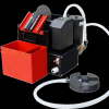
YHB Disk-type Oil Skimmer
YHB Disk-type Oil Skimmer Disc Type Oil Skimmer Belt Type Oil Skimmer, Disc type Disc Type Oil Skimmer Oil skimmer ·∫∫®“π „™È·¬°πÈ”¡—πÀ≈ËÕ≈◊Ëπ (Tramp oil) ∑’Ë≈Õ¬Õ¬ŸË∫ππÈ”¡—πÀ≈ËÕý¬Áπ ýÀ¡“–∑’Ë®–µ‘¥µ—Èß∫π∂—ßπÈ”¡—πÀ≈ËÕý¬Áπ¢Õßý§√◊ËÕß CNC Disc Oil Skimmers, Oil Skimmers, Disc Type Oil Skimmers Oil Skimmer ý§√◊ËÕߥŸ¥§√“∫πÈ”¡—π·∫∫ý§≈◊ËÕπ∑’Ë „™Èß“πßË“¬ –¥«°
YHB Disk-type Oil Skimmer Disc Type Oil Skimmer Belt Type Oil Skimmer, Disc type Disc Type Oil Skimmer Oil skimmer ·∫∫®“π „™È·¬°πÈ”¡—πÀ≈ËÕ≈◊Ëπ (Tramp oil) ∑’Ë≈Õ¬Õ¬ŸË∫ππÈ”¡—πÀ≈ËÕý¬Áπ ýÀ¡“–∑’Ë®–µ‘¥µ—Èß∫π∂—ßπÈ”¡—πÀ≈ËÕý¬Áπ¢Õßý§√◊ËÕß CNC Disc Oil Skimmers, Oil Skimmers, Disc Type Oil Skimmers Oil Skimmer ý§√◊ËÕߥŸ¥§√“∫πÈ”¡—π·∫∫ý§≈◊ËÕπ∑’Ë „™Èß“πßË“¬ –¥«°
Last Update : 08/09/2023 07:28:13

Tools presetter ý§√◊ËÕß«—¥√–¬–À—«°—¥ CNC ¡‘≈≈‘Ëß ®“°ª√–ý∑»ý¬Õ√¡π’
Tools presetter ý§√◊ËÕß«—¥√–¬–À—«°—¥ CNC ¡‘≈≈‘Ëß ý§√◊ËÕßý´ÁµÕÿª°√≥Ï ”À√—∫ý§√◊ËÕß®—°√ KELCH Tool presetting ®“°ª√–ý∑»ý¬Õ√¡π’
Tools presetter ý§√◊ËÕß«—¥√–¬–À—«°—¥ CNC ¡‘≈≈‘Ëß ý§√◊ËÕßý´ÁµÕÿª°√≥Ï ”À√—∫ý§√◊ËÕß®—°√ KELCH Tool presetting ®“°ª√–ý∑»ý¬Õ√¡π’
Last Update : 25/07/2023 13:10:13
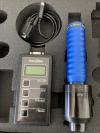
KELCH Safecontrol 4.0 Force Check
KELCH Safecontrol 4.0 Force Check for spindle force BT30 BT40 BT50 HSK25 HSK32 HSK40 HSK50 HSK63 HSK100
KELCH Safecontrol 4.0 Force Check for spindle force BT30 BT40 BT50 HSK25 HSK32 HSK40 HSK50 HSK63 HSK100
Last Update : 24/07/2023 15:36:12
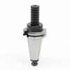
ForceCheck - TAC Rockford
ForceCheck - TAC Rockford ForceCheck HSK Taper Drawbar Force Gauges For measuring drawbar retention force on HSK (Hollow-Shank Taper) standard spindles
ForceCheck - TAC Rockford ForceCheck HSK Taper Drawbar Force Gauges For measuring drawbar retention force on HSK (Hollow-Shank Taper) standard spindles
Last Update : 23/07/2023 08:40:34
Polygon Solutions Rotary Broach Tools T-40 Torx GO and NOGO Gage Set
Rotary Broaches Rotary Broach Tool Holders Go & NoGo Gages Torx Rotary Broaches Rotary Broach Tool Holders Go & NoGo Gages Hexagon (Hex) Go/NoGo Gages Square Go/No-Go Gauges Hexalobular Go/NoGo Gages T-40 Torx GO and NOGO Gage Set
Rotary Broaches Rotary Broach Tool Holders Go & NoGo Gages Torx Rotary Broaches Rotary Broach Tool Holders Go & NoGo Gages Hexagon (Hex) Go/NoGo Gages Square Go/No-Go Gauges Hexalobular Go/NoGo Gages T-40 Torx GO and NOGO Gage Set
Last Update : 21/07/2023 17:35:40

Branson ý§√◊ËÕßý™◊ËÕ¡ “¬‰øøÈ“ ”À√—∫‚√ßß“π®“°ª√–ý∑»Õý¡√‘°“
Branson ý§√◊ËÕßý™◊ËÕ¡ “¬‰øøÈ“ ”À√—∫‚√ßß“π®“°ª√–ý∑»Õý¡√‘°“
Branson ý§√◊ËÕßý™◊ËÕ¡ “¬‰øøÈ“ ”À√—∫‚√ßß“π®“°ª√–ý∑»Õý¡√‘°“
Last Update : 19/07/2023 15:44:04

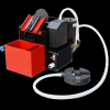
Branson ý§√◊ËÕß≈È“ßÕÿ≈µ√È“‚´π‘°®“°ª√–ý∑» À√—∞ USA §ÿ≥¿“æ Ÿß
Branson | Welding & Cleaning Equipment ý§√◊ËÕß∑”§«“¡ –Õ“¥Õ—≈µ√“‚´π‘° Ultrasonic „πß“π‚√ßß“πÕÿµ “À°√√¡ Ultrasonic Cleaner §◊ÕÕÿª°√≥Ï∑”§«“¡ –Õ“¥∑’Ë„™È§≈◊Ë𧫓¡∂’Ë ŸßÕ—≈µ√È“´“«¥Ï ∫√‘…—∑¢“¬ý§√◊ËÕß≈È“ßÕ—≈µ√È“‚´π‘§. Ultrasonic Cleaner ∂Ÿ°„™È„πÕÿµ “À°√√¡ Ultrasonic Cleaner (ý§√◊ËÕß≈ȓߧ«“¡∂’Ë Ÿß)
Branson | Welding & Cleaning Equipment ý§√◊ËÕß∑”§«“¡ –Õ“¥Õ—≈µ√“‚´π‘° Ultrasonic „πß“π‚√ßß“πÕÿµ “À°√√¡ Ultrasonic Cleaner §◊ÕÕÿª°√≥Ï∑”§«“¡ –Õ“¥∑’Ë„™È§≈◊Ë𧫓¡∂’Ë ŸßÕ—≈µ√È“´“«¥Ï ∫√‘…—∑¢“¬ý§√◊ËÕß≈È“ßÕ—≈µ√È“‚´π‘§. Ultrasonic Cleaner ∂Ÿ°„™È„πÕÿµ “À°√√¡ Ultrasonic Cleaner (ý§√◊ËÕß≈ȓߧ«“¡∂’Ë Ÿß)
Last Update : 19/07/2023 15:33:24
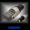
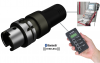
YAMAZAKI Pullmeter YPM30 YPM40 YPM50
YAMAZAKI Pullmeter Yamazaki push-pull meter pull meter YPM01 YPM40 YPM50 Pull stud BT40 for Yamazaki YPM-50 YPM-40 YPM-30 YPM-KSK63A YPM-KM10080 YMP-KM6350 π„®µ‘¥µËÕ [email protected];[email protected] : Mobile : K.¿Ÿ√‘π∑√Ï 098-4288648 Line ID : 0984288648
YAMAZAKI Pullmeter Yamazaki push-pull meter pull meter YPM01 YPM40 YPM50 Pull stud BT40 for Yamazaki YPM-50 YPM-40 YPM-30 YPM-KSK63A YPM-KM10080 YMP-KM6350 π„®µ‘¥µËÕ [email protected];[email protected] : Mobile : K.¿Ÿ√‘π∑√Ï 098-4288648 Line ID : 0984288648
Last Update : 17/07/2023 18:09:32

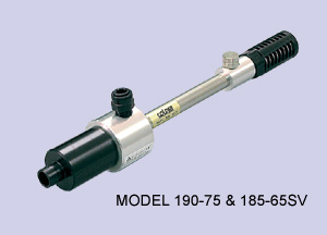
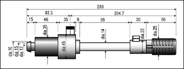
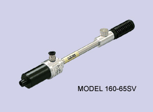
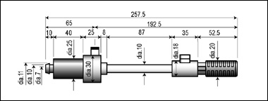
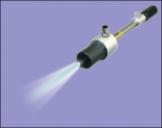
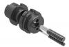
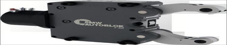
µ—«·∑π®”ÀπË“¬ ‘π§È“ OTT-JAKOB Power-Check 2
Brand : OTT-JAKOB
µ—«·∑π®”ÀπË“¬ ‘π§È“ OTT-JAKOB Power-Check 2 OTT-JAKOB POWER-CHECK ý§√◊ËÕß¡◊Õ«—¥·√ߥ÷ߢÕßý§√◊ËÕß®—°√ CNC Machining Center
µ—«·∑π®”ÀπË“¬ ‘π§È“ OTT-JAKOB Power-Check 2 OTT-JAKOB POWER-CHECK ý§√◊ËÕß¡◊Õ«—¥·√ߥ÷ߢÕßý§√◊ËÕß®—°√ CNC Machining Center
Last Update : 11:43:17 14/05/2024

Universal Punch ý§√◊ËÕß«—¥§Ë“§«“¡√Ë«¡»Ÿπ¬Ï
Brand : ý§√◊ËÕß«—¥§Ë“§«“¡√Ë«¡»Ÿπ¬Ï ”À√—∫™‘Èπß“π°≈¡ Concentricity Gage
Universal Punch ý§√◊ËÕß«—¥§Ë“§«“¡√Ë«¡»Ÿπ¬Ï ”À√—∫™‘Èπß“π°≈¡ Concentricity Gage A-10 Universal Punch Concentricity Gage B-40 Universal Punch Concentricity Gage E-40 Universal Punch Concentricity Gage G1-10 Universal Punch Concentricity Gage E-10 Universal Punch Concentricity Gage E-40 Universal Punch Concentricity Gage HL-40 Universal Punch Concentricity Gag J-10 Universal Punch Concentricity Gage H-20 Universal Punch Concentricity Gage H-10 Universal Punch Concentricity Gage G2-20 Universal Punch Concentricity Gage B-20 Universal Punch Concentricity Gage H-40 Universal Punch Concentricity Gage H-20 Universal Punch Concentricity Gage H-10 Universal Punch Concentricity Gage G2-40 Universal Punch Concentricity Gage G2-20 Universal Punch Concentricity Gage G2-10 Universal Punch Concentricity Gage G1-40 Universal Punch Concentricity Gage G1-20 Universal Punch Concentricity Gage G1-10 Universal Punch Concentricity Gage F-20 Universal Punch Concentricity Gage F-10 Universal Punch Concentricity Gage E-40 Universal Punch Concentricity Gage E-20 Universal Punch Concentricity Gage E-10 Universal Punch Concentricity Gage B-40 Universal Punch Concentricity Gage B-20 Universal Punch Concentricity Gage B-10 Universal Punch Concentricity Gage A-10 Universal Punch Concentricity Gage KK1-40 Universal Punch Concentricity Gage KK1-20 Universal Punch Concentricity Gage KK1-10 Universal Punch Concentricity Gage K2-40 Universal Punch Concentricity Gage K2-20 Universal Punch Concentricity Gage K2-10 Universal Punch Concentricity Gage K1-40 Universal Punch Concentricity Gage K1-20 Universal Punch Concentricity Gage K1-10 Universal Punch Concentricity Gage JSLP-10C Universal Punch Concentricity Gage JSLP-10 Universal Punch Concentricity Gage JLP-10 Universal Punch Concentricity Gage J-40 Universal Punch Concentricity Gage J-20 Universal Punch Concentricity Gage J-10 Universal Punch Concentricity Gage HL-40 Universal Punch Concentricity Gage HL-20 Universal Punch Concentricity Gage HL-10 Universal Punch Concentricity Gage LG-20 Universal Punch Concentricity Gage LG-10 Universal Punch Concentricity Gage KK2-40 Universal Punch Concentricity Gage KK2-20 Universal Punch Concentricity Gage KK2-10 Universal Punch Concentricity Gage
Universal Punch ý§√◊ËÕß«—¥§Ë“§«“¡√Ë«¡»Ÿπ¬Ï ”À√—∫™‘Èπß“π°≈¡ Concentricity Gage A-10 Universal Punch Concentricity Gage B-40 Universal Punch Concentricity Gage E-40 Universal Punch Concentricity Gage G1-10 Universal Punch Concentricity Gage E-10 Universal Punch Concentricity Gage E-40 Universal Punch Concentricity Gage HL-40 Universal Punch Concentricity Gag J-10 Universal Punch Concentricity Gage H-20 Universal Punch Concentricity Gage H-10 Universal Punch Concentricity Gage G2-20 Universal Punch Concentricity Gage B-20 Universal Punch Concentricity Gage H-40 Universal Punch Concentricity Gage H-20 Universal Punch Concentricity Gage H-10 Universal Punch Concentricity Gage G2-40 Universal Punch Concentricity Gage G2-20 Universal Punch Concentricity Gage G2-10 Universal Punch Concentricity Gage G1-40 Universal Punch Concentricity Gage G1-20 Universal Punch Concentricity Gage G1-10 Universal Punch Concentricity Gage F-20 Universal Punch Concentricity Gage F-10 Universal Punch Concentricity Gage E-40 Universal Punch Concentricity Gage E-20 Universal Punch Concentricity Gage E-10 Universal Punch Concentricity Gage B-40 Universal Punch Concentricity Gage B-20 Universal Punch Concentricity Gage B-10 Universal Punch Concentricity Gage A-10 Universal Punch Concentricity Gage KK1-40 Universal Punch Concentricity Gage KK1-20 Universal Punch Concentricity Gage KK1-10 Universal Punch Concentricity Gage K2-40 Universal Punch Concentricity Gage K2-20 Universal Punch Concentricity Gage K2-10 Universal Punch Concentricity Gage K1-40 Universal Punch Concentricity Gage K1-20 Universal Punch Concentricity Gage K1-10 Universal Punch Concentricity Gage JSLP-10C Universal Punch Concentricity Gage JSLP-10 Universal Punch Concentricity Gage JLP-10 Universal Punch Concentricity Gage J-40 Universal Punch Concentricity Gage J-20 Universal Punch Concentricity Gage J-10 Universal Punch Concentricity Gage HL-40 Universal Punch Concentricity Gage HL-20 Universal Punch Concentricity Gage HL-10 Universal Punch Concentricity Gage LG-20 Universal Punch Concentricity Gage LG-10 Universal Punch Concentricity Gage KK2-40 Universal Punch Concentricity Gage KK2-20 Universal Punch Concentricity Gage KK2-10 Universal Punch Concentricity Gage
Last Update : 17:55:32 23/02/2024
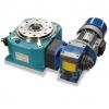
®”ÀπË“¬ Mechanical rotary tables
Brand : Mechanical rotary tables
®”ÀπË“¬ Mechanical rotary tables π„® ‘π§È“ Õ∫∂“¡∑’˧ÿ≥¿Ÿ√‘π∑√Ï 0984288648
®”ÀπË“¬ Mechanical rotary tables π„® ‘π§È“ Õ∫∂“¡∑’˧ÿ≥¿Ÿ√‘π∑√Ï 0984288648
Last Update : 09:15:13 18/12/2023
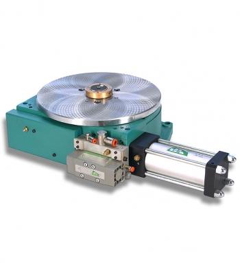
Pneumatic rotary tables °√–∫Õ°≈¡·∫∫À¡ÿπ≈ÁÕ§µ”·ÀπËß
Brand : Pneumatic rotary tables
Pneumatic rotary tables °√–∫Õ°≈¡·∫∫À¡ÿπ≈ÁÕ§µ”·ÀπËß‚¥¬„™È≈¡ G.P.A. Italiana pneumatic rotary indexing tables are available in two versions: TAR 270 and TAR 160 ¢π“¥‚µÍ–À¡ÿπ¡’ Õß·∫∫ 160 mm 270 mm
Pneumatic rotary tables °√–∫Õ°≈¡·∫∫À¡ÿπ≈ÁÕ§µ”·ÀπËß‚¥¬„™È≈¡ G.P.A. Italiana pneumatic rotary indexing tables are available in two versions: TAR 270 and TAR 160 ¢π“¥‚µÍ–À¡ÿπ¡’ Õß·∫∫ 160 mm 270 mm
Last Update : 09:12:10 18/12/2023
Carbide insert
Brand : KHAN
Model : Work Gripper Carbide insert : PC127-10SC PC127-4SC PC130-4SC PC145-5SC PC132-4SC PC070-12SC PC070-4SC PC130-2SC-S PC127-4SC-S
ø—π®‘°™‘Èπß“π ”À√—∫ß“πÀ≈ËÕ Carbide insert PC127-4SC-S PC127-2SC-S PC130-2SC-S PC132-2SC-S PC070-12SC PC070-4SC PC046-4SC PC050-4SC Carbide Insert : PC-127-4SC-S : SOUL
Last Update : 10:12:51 01/11/2023
®”ÀπË“¬∂Ë“π≈‘ý∏’¬¡ ·∫µýµÕ√’Ë SAFT LS14250 for RENISHAW
Brand : SAFT LS14250 for RENISHAW
∂Ë“π≈‘ý∏’¬¡ ·∫µýµÕ√’Ë Saft LS14250 Lithium Battery 3.6V ¢Õß·∑È„™Èß“π‰¡Ë‰¥È ¬‘π¥’§◊πýß‘π SAFT LS 14250 3.6V 1/2 AA Primary Lithium Battery ¢Õß·∑È 100% SAFT for RENISHAW
∂Ë“π≈‘ý∏’¬¡ ·∫µýµÕ√’Ë Saft LS14250 Lithium Battery 3.6V ¢Õß·∑È„™Èß“π‰¡Ë‰¥È ¬‘π¥’§◊πýß‘π SAFT LS 14250 3.6V 1/2 AA Primary Lithium Battery ¢Õß·∑È 100% SAFT for RENISHAW
Last Update : 17:38:16 26/10/2023
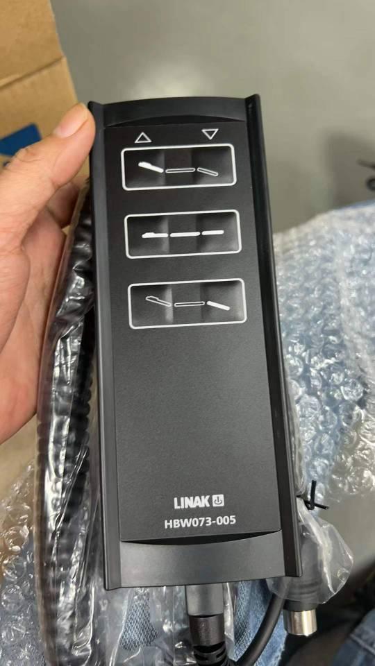
√’‚¡∑ýµ’¬ß‰øøÈ“ LINAK Handset
Brand : √’‚¡∑ýµ’¬ß‰øøÈ“ LINAK Handset
√’‚¡∑ýµ’¬ß‰øøÈ“ LINAK Handset HBW073-005 HB80 HD80 ®”ÀπË“¬ ‘π§È“¢Õ߬’ËÀÈÕ LINAK actuator systems √’‚¡∑ýµ’¬ß‰øøÈ“ Õ–‰À≈Ë√’‚¡∑ ”À√—∫ýµ’¬ßºŸÈªË«¬ª√—∫¥È«¬‰øøÈ“
√’‚¡∑ýµ’¬ß‰øøÈ“ LINAK Handset HBW073-005 HB80 HD80 ®”ÀπË“¬ ‘π§È“¢Õ߬’ËÀÈÕ LINAK actuator systems √’‚¡∑ýµ’¬ß‰øøÈ“ Õ–‰À≈Ë√’‚¡∑ ”À√—∫ýµ’¬ßºŸÈªË«¬ª√—∫¥È«¬‰øøÈ“
Last Update : 14:17:03 17/10/2023
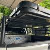
™ÿ¥·√Á§§“π¢«“ß«“ßýµÁπ∑ÏÀ≈—ߧ“ (§Õ°ÕÕø‚√¥«“ßýµÁπ∑ÏÀ≈—ߧ“)
Brand : ™ÿ¥·√Á§§“π¢«“ß«“ßýµÁπ∑ÏÀ≈—ߧ“ REVO VIGO ISUZU Mitsubishi FORD
§Õ°ÕÕø‚√¥«“ßýµÁπ∑ÏÀ≈—ߧ“ ·√Á§«“ßýµÁπ∑Ï Õÿª°√≥Ïý √‘¡√∂°√–∫– ”À√—∫ “¬·§¡ª‘Èß ·√Á§À≈—ߧ“ MOUNTAIN TOP µ‘¥µ—ÈßßË“¬ ‰¡ËµÈÕßý®“–µ—«√∂ Roof Top Tent Parking ‚√∫“√Ï ý∫¥·√Á§ «“ßýµÁπ∑Ï µ‘¥‰¥È°—∫√∂°√–∫–∑ÿ°√ÿËπ ‚√∫“√Ï«“ßýµÁπ∑ÏÀ≈—ߧ“ ¥·√Á§§“π¢«“ß «“ßýµÁπ∑ÏÀ≈—ߧ“ ”À√—∫√∂√ÿËπ √’‚«Ë REVO VIGO ISUZU Mitsubishi FORD
§Õ°ÕÕø‚√¥«“ßýµÁπ∑ÏÀ≈—ߧ“ ·√Á§«“ßýµÁπ∑Ï Õÿª°√≥Ïý √‘¡√∂°√–∫– ”À√—∫ “¬·§¡ª‘Èß ·√Á§À≈—ߧ“ MOUNTAIN TOP µ‘¥µ—ÈßßË“¬ ‰¡ËµÈÕßý®“–µ—«√∂ Roof Top Tent Parking ‚√∫“√Ï ý∫¥·√Á§ «“ßýµÁπ∑Ï µ‘¥‰¥È°—∫√∂°√–∫–∑ÿ°√ÿËπ ‚√∫“√Ï«“ßýµÁπ∑ÏÀ≈—ߧ“ ¥·√Á§§“π¢«“ß «“ßýµÁπ∑ÏÀ≈—ߧ“ ”À√—∫√∂√ÿËπ √’‚«Ë REVO VIGO ISUZU Mitsubishi FORD
Last Update : 14:12:42 30/09/2023
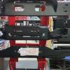
∂“¥«‘π´Ï´ËÕπ°—π™πý¥‘¡ √’‚«Ë REVO VIGO ISUZU Mitsubishi FORD
Brand : ∂“¥«‘π´Ï´ËÕπ°—π™πý¥‘¡
∂“¥«‘π´Ï´ËÕπ°—π™πý¥‘¡ Mitsubishi TRITON √’‚«Ë REVO «’‚°È VIGO ISUZU Mitsubishi FORD Ranger ∂“¥«‘π´Ï Revo ´ËÕπ°—π™πý¥‘¡
∂“¥«‘π´Ï´ËÕπ°—π™πý¥‘¡ Mitsubishi TRITON √’‚«Ë REVO «’‚°È VIGO ISUZU Mitsubishi FORD Ranger ∂“¥«‘π´Ï Revo ´ËÕπ°—π™πý¥‘¡
Last Update : 08:45:29 30/09/2023


KOIKE Oil Skimmer
Brand : KOIKE Oil Skimmer
KOIKE Oil Skimmer Belt Type Oil Skimmer ÕÕ¬ °‘¡ý¡Õ√Ï ·¬°ºßý»…ýÀ≈Á°∑’Ë¡“æ√ÈÕ¡°—∫πÈ”¡—πÀ≈ËÕý¬Áπý§√◊ËÕß®—°√ KOCV-130 KOCV-220 KOCV-320 JS25-115B JS25-200B JS25-300B SOC-165A SOC-250A SOC-350A
KOIKE Oil Skimmer Belt Type Oil Skimmer ÕÕ¬ °‘¡ý¡Õ√Ï ·¬°ºßý»…ýÀ≈Á°∑’Ë¡“æ√ÈÕ¡°—∫πÈ”¡—πÀ≈ËÕý¬Áπý§√◊ËÕß®—°√ KOCV-130 KOCV-220 KOCV-320 JS25-115B JS25-200B JS25-300B SOC-165A SOC-250A SOC-350A
Last Update : 10:01:12 23/09/2023
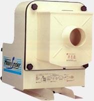
Mist collector Heavy Smoker ?
Brand : ONIKAZE HEAVY SMOKER
Model : ONIKAZE HEAVY SMOKER Mist collector HVS-40/HVS-100/HVS-150/HVS-220/HVS-300/HVS-2500
HVS-150 HVS-40 HVS-40 HVS-40 HVS-40 HVS-40
Model : ONIKAZE HEAVY SMOKER Mist collector HVS-40/HVS-100/HVS-150/HVS-220/HVS-300/HVS-2500
HVS-150 HVS-40 HVS-40 HVS-40 HVS-40 HVS-40
Last Update : 14:10:21 22/09/2023
ROTARY AIR CHUCK
Brand : ROTARY AIR CHUCK
KOBAYASHI ROTARY AIR CHUCK VICTOR CHUCK VICTOR CHUCK SAC-4B3 RAC-4B3 RAC-5B3 RAC-6B3 RAC-5 RAC-6 RAC-8 RAC-10 RAC-12 RAC-4B3 RAC-5B3 RAC-6B3 TV-03 TV-05 TV-06
KOBAYASHI ROTARY AIR CHUCK VICTOR CHUCK VICTOR CHUCK SAC-4B3 RAC-4B3 RAC-5B3 RAC-6B3 RAC-5 RAC-6 RAC-8 RAC-10 RAC-12 RAC-4B3 RAC-5B3 RAC-6B3 TV-03 TV-05 TV-06
Last Update : 11:21:37 20/09/2023
ÕÕ¬ °‘¡ý¡Õ√Ï Disk-type Oil Skimmer
Brand : YHB Disk-type Oil Skimmer
ÕÕ¬ °‘¡ý¡Õ√Ï Disk-type Oil Skimmer Coolant Chip cleaner(Portable) Coolant Chip cleaner Coolant Sludge cleaner
ÕÕ¬ °‘¡ý¡Õ√Ï Disk-type Oil Skimmer Coolant Chip cleaner(Portable) Coolant Chip cleaner Coolant Sludge cleaner
Last Update : 10:55:18 19/09/2023


|
π—∫ πÿπ‚¥¬ °√¡ Ëßý √‘¡Õÿµ “À°√√¡ °√–∑√«ßÕÿµ “À°√√¡


|
||||||||||||||||||||||||||||||||||||||||||||||||||||||||||||||||||||||||||||||||||||||||||||||||||||||||||||||||||||||||||||||||||||||||||||||||||||||||||||||||||||||||||||||||||||||||||||||||||||||||||||||||||||||||||||||||||||||||||||||||||||||||||||||||||||||||||||||||||||||||||||||||||||||||||||||||||||||||||||||||||||||||||||||||||||||||||||||||||||||||||||||||||||||||||||||||||||||||||||||||||||||||||||||||||||||||||||||||||||||||||||||||||||||||||||||||||||||||||||||||||||||||||||||||||||||||||||||||||||||||||||||||||||||